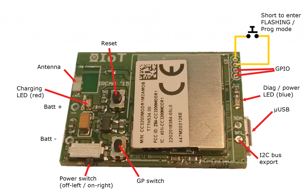
The R-IoT sensor module embeds a ST Microelectronics 9 axis sensor with 3 accelerometers, 3 gyroscopes and 3 magnetometers, all 16 bit. The data are sent wirelessly (WiFi) using the OSC protocol.
The core of the board is a Texas Instrument WiFi module with a 32 bit Cortex ARM processor that execute the program and deals with the Ethernet / WAN stack. It is compatible with TI’s Code Composer and with Energia, a port of the Arduino environment for TI processors.
Processing modules can be found here.
We also provide firmware and processing modules to be uploaded in the RiOT, and Max patches (to use with the free MuBu library), to directly get the data stream into Max and analyse or detect specific motion patterns (free fall, spinning, shaking…).
Codes and Max pataches can be find the following GitHub https://github.com/Ircam-RnD/RIoT.
Energia version 16 should be used to compile and flash the current firmware.
A guide for programming and flashing the R-IoT module is available here : R-IoT Programming & Flashing Guide.
Specs :
How to configure a WiFi Access point to receive data from R-IoT
While it’s possible to connect the computer by WiFi to the AP, we strongly advise to use wired Ethernet as it maximizes the throughput and reduces both the latency and data jitter.
When taken straight out of the box, the AP is usually configured with DHCP enabled for clients and with a fixed IP address which can be (most of the time) 192.168.1.1 or 192.168.0.1 or in the case or the mini TP-link 3G/Wifi router, 192.168.0.254.
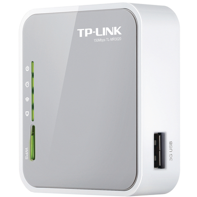
Set your computer in DHCP (aka “obtain an IP automatically”) and connect it to the router by wired ethernet. Based on the address type you’ll receive (either 1.xxx or 0.xxx) connect to either 192.168.1.1 or 192.168.0.1 or… RTFM ;-) Sometimes DHCP is disabled by default, and a manually set IP address must be assigned to the computer using the same scheme of the router’s default address. In the case of the small TP-link pocket router above, the computer can be set to 192.168.0.100 to first access the admin page located on 192.168.0.254.
When accessing the AP, you’ll be prompted for a login and password, the provided routers are left with admin / admin. Once in the administration page of the access point, there are only a few things to setup. All those things can be changed and tuned to match any equipment, we’re just covering here the basics.
– The default configuration of R-IoT is to connect to a computer with the fixed IP address 192.168.1.100. If the router / AP configuration is set to 192.168.0.1, there will be an address mismatch, therefore go in the Network -> LAN page and change the AP address to 192.168.1.1 or 192.168.1.254 which is kind of standard
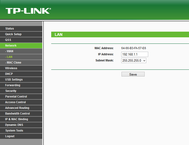
That will usually require a reboot of the AP, proceed and log in once again.
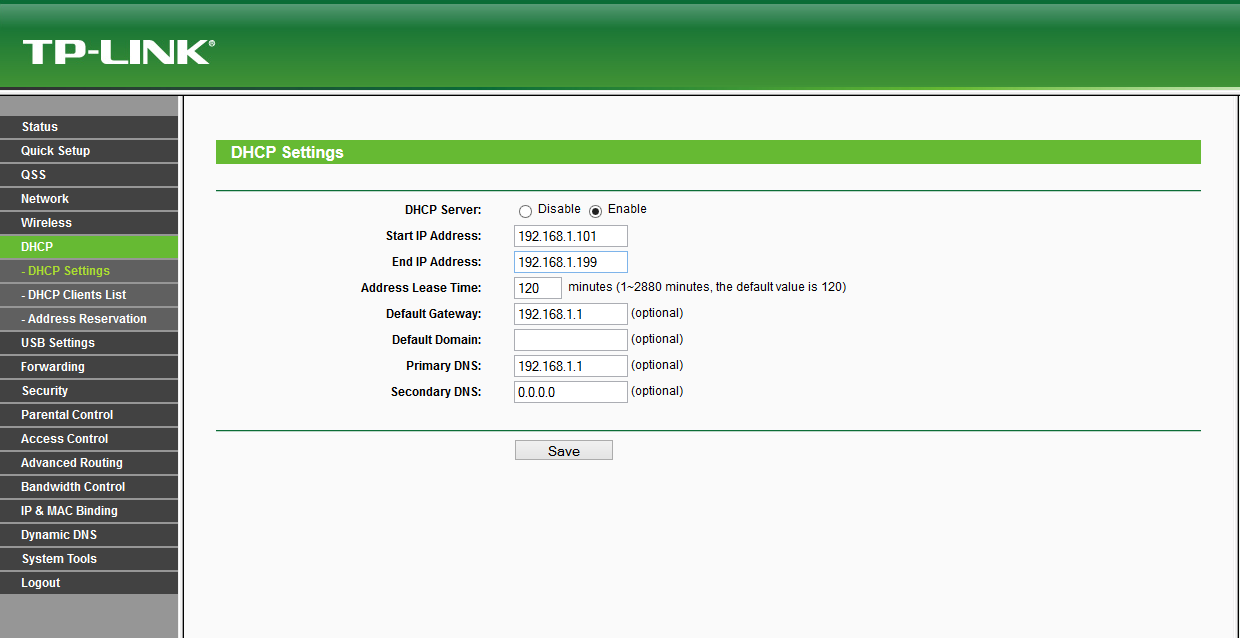
– Tune the DHCP settings. Most of the time the DHCP will be active on addresses from 192.168.1.100 to 199. Change this from 110 to 150, anything to avoid having the default destination IP address (192.168.1.100) to be in the DHCP lease pit. Alternatively you can leave it in the DHCP area and reserve the address based on the MAC address of your computer (see DHCP address reservation)
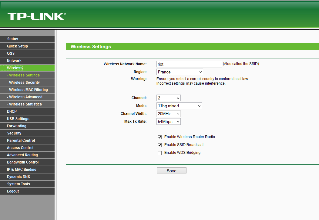
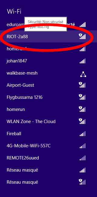
– Finally go in the Wireless settings, change the SSID of your network. Each provided module has a sticker on with with its serial #. Each number matches a SSID name “riotXX” (module number 5 wants to connect to riot5). Select a wifi channel that is possibly different than your neighbor. Finally, go in the security section and disable encryption (WPA2 encryption is supported but not recommended on first use).
Once the router is configured with this 192.168.1.xxx address scheme and DHCP, the computer can be set to 192.168.1.100, the default destination address the R-IoT module sends data to.
For #MFT scandi, we had pre configured alls provided pocket routers. The can be already accessed via 192.168.1.254 and have a SSID / wifi network name matching the # of the provided R-IoT module (riot3 for module #3 etc). Overall, there’s no standard for naming your SSID, the only requirement is to have the R-IoT SSID name configuration matching the AP SSID.
The WiFi radio channel can be adjusted in order to limit bandwith occupation. Each router has been assigned to a different channel (double check). Use a scanner or just use any WiFi survey app out there to diagnose the RF space around your spot and select the less busy channel.
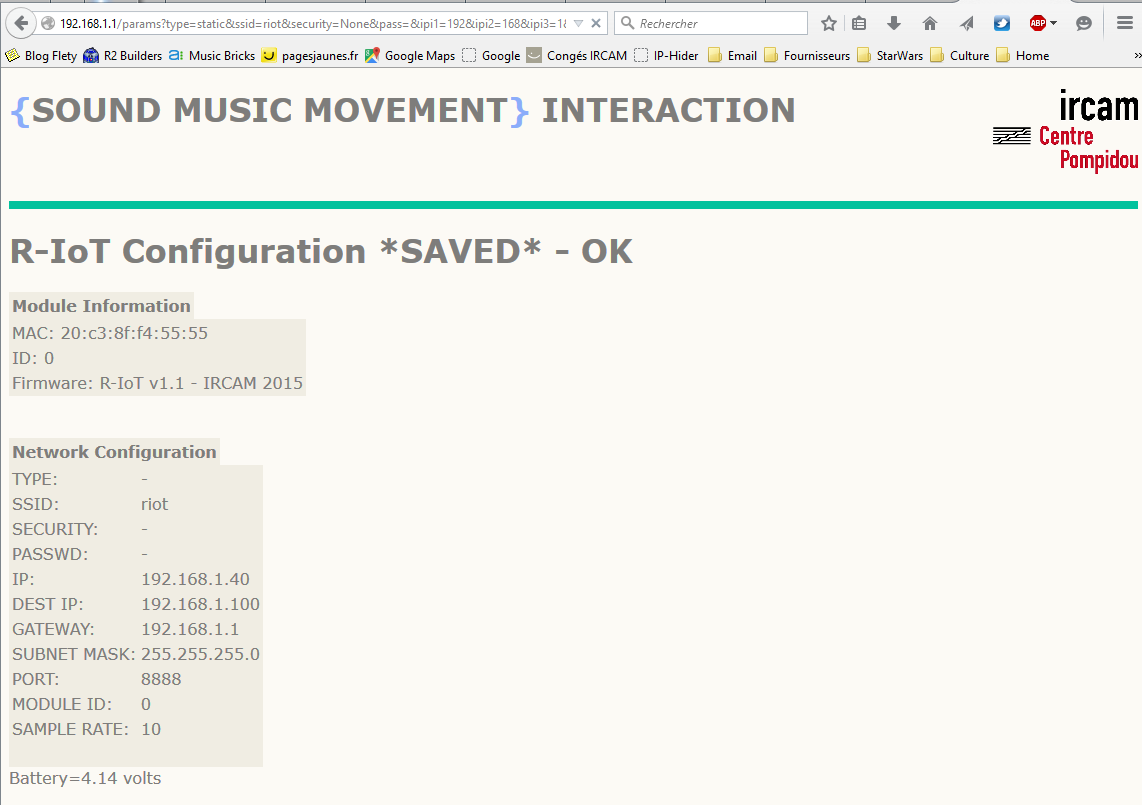
Accessing the Web Server for configuring the module
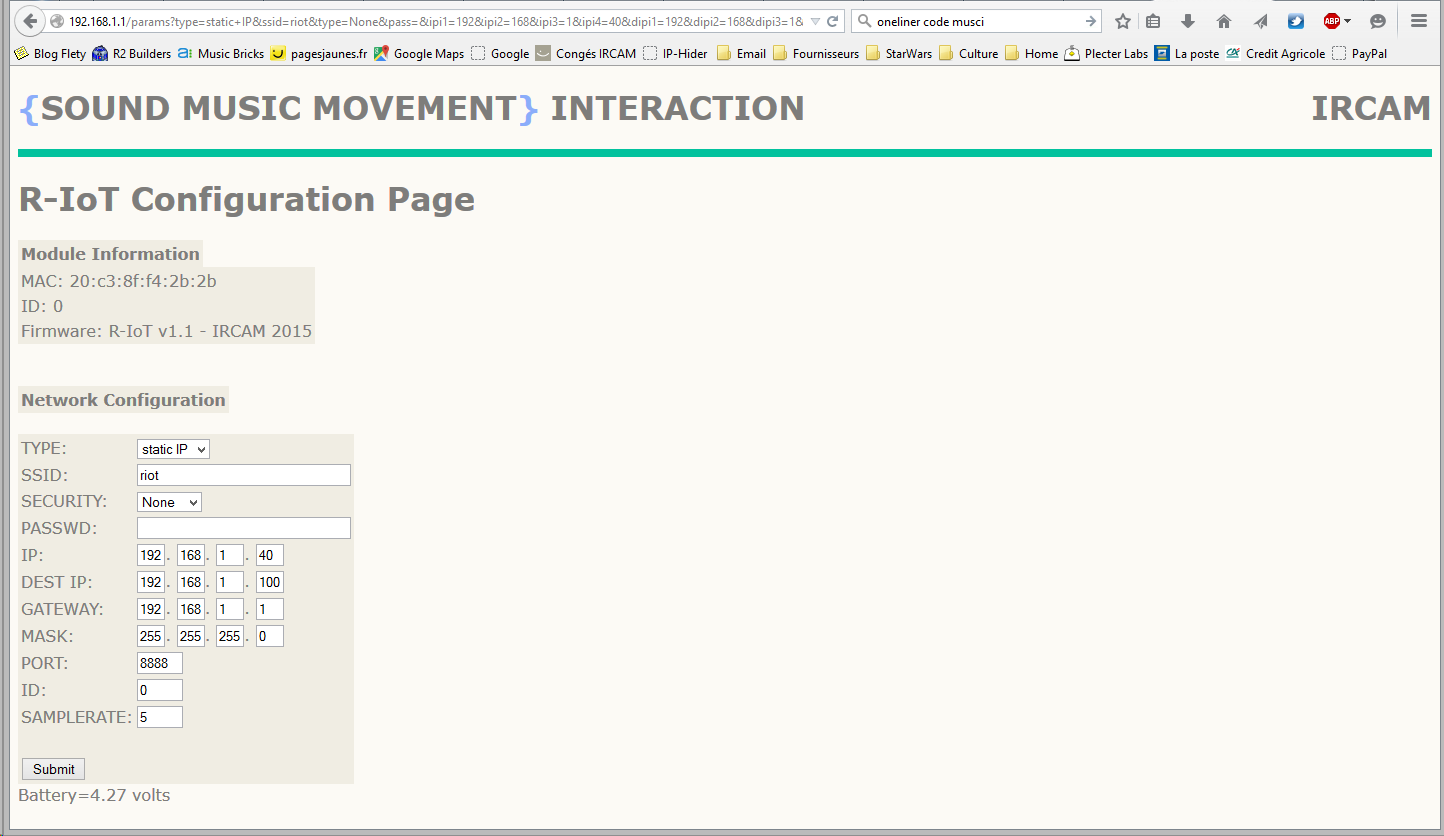
Currently, the IP address type remains DHCP in the current version of the firmware until Energia stabilizes its API, and security isn’t implemented yet neither. The main parameters that can be adjusted are the IP address of the computer to connect to (DEST IP), the UDP Port, the ID of the module and the sample rate (min 3 ms).
The ID is used to compose the Open Sound Control address scheme which looks like /<ID>/<stream> followed by a data list. When using several modules on the same WiFi access point, the best practice is to :
Once the module configuration is finished, press the submit button, settings will be saved in the non volatile memory of the module that then has to be rebooted to apply the new configuration.
Receive sensors data from the module
Below is an data receiving in max-msp. The module currently forges 3 OSC packets